
Wide-Input Isolated IGBT Gate-Drive Fly-Buck Power Supply for Three-Phase Inverters Reference Design
Description
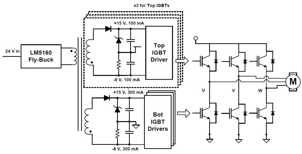
This reference design provides isolated positive and negative voltage rails required for Insulated Gate Bipolar Transistor (IGBT) gate drivers from a single 24-volt DC input supply. Utilizing a Fly-Buck™ control topology: this reference design uses a single transformer for generating power rails for all three arms of the 3-phase inverter. It uses primary-side regulation and can achieve good cross regulation without opto-coupler feedback or an auxiliary winding. The isolated outputs are generated through the coupled windings of the transformer. The voltage rails for all the high-side IGBTs are individually isolated: whereas the voltage rails for all low-side IGBTs are combined.
Features
- • Isolated power supply with 24V±20% input range that supports 6 IGBT gate drivers for 3-phase inverter (each arm in half-bridge configuration)• Low-ripple (• Fly-Buck topology provides easy-to-design multi-output isolated power supply solution with primary side regulation• Peak efficiency of 82% at balanced full-load• Output capacitors rated to support up to 6A peak gate drive current
Applications
- String inverter
- AC drive power stage module
- AC-input BLDC motor drive
- HVAC controller
- Three phase UPS
- Textile machine
- Printing & paper machine
- Servo drive power stage module
- Servo drive power supply module
- DC fast charging station
- Railway auxiliary power
- Railway electric propulsion
- Traction inverter motor control
- HVAC motor control
- HVAC valve & actuator control
- DC fast charging power module
- Injection molding machine
- Robot servo drive
Product Categories
- Power management
| Title | Updated | Type | Size (KB) |
|---|---|---|---|
| Analysis of Power Supply Topologies for IGBT Gate Drivers in Industrial Drives | 06 Jul 2015 | 7246 | |
| Is Your IGBT Gate-Driver Power Supply Optimized | 12 Mar 2015 | 115 |
| Download the bill of materials for TIDA-00199 | Download |
Test Data

Get results faster with test and simulation data that's been verified.
Download the test file for TIDA-00199| Title | Updated | Type | Size (KB) | |
|---|---|---|---|---|
| TIDA-00199 Gerber | 19 Dec 2014 | ZIP | 348 | |
| TIDA-00199 CAD Files | 19 Dec 2014 | ZIP | 1352 | |
| TIDA-00199 PCB | 19 Dec 2014 | 733 | ||
| TIDA-00199 Assembly Drawing | 19 Dec 2014 | 148 | ||
| TIDA-00199 BOM | 19 Dec 2014 | 61 | ||
| TIDA-00199 Schematic | 19 Dec 2014 | 186 |